[Future Technology Research Index]
[SGI Tech/Advice Index]
[Nintendo64 Tech Info Index]
[WhatsNew]
[P.I.]
[Indigo]
[Indy]
[O2]
[Indigo2]
[Crimson]
[Challenge]
[Onyx]
[Octane]
[Origin]
[Onyx2]
(check my current auctions!)

RealityEngine in Visual Simulation
Technical Overview
Table of Contents
Section 1: Abstract
Section 2: Introduction
-
2.1 Product Overview
2.2 A New Image Generator Approach
-
2.2.1 The Next Generation of Image Generators
2.2.2 IRIS Performer and Reality Engine
2.3 Applications
Section 3: Hardware Architecture
-
3.1 Architectural Overview
-
3.1.1 The Geometry Engine
3.1.2 The Raster Manager
3.1.3 Display Subsystem
3.1.4 VideoSplitter/2
3.2 Chassis Configuration
-
3.2.1 Deskside Chassis
3.2.2 SkyWriter Rack Chassis
3.2.3 POWER Series Rack Rack Chassis
Section 4: Configuration
-
4.1 System Configuration
4.2 Graphics Board Level Options
Section 5: Features and Performance
-
5.1 Overall System Performance
5.2 Texture
-
5.2.1 Components
5.2.2 Texture Memory Configuration
5.3 Types and Methods
-
5.3.1 Non MIPmapped Texture Functions
5.3.2 MIPmapped Texture Functions
5.3.3 Texture Performance
5.4 Anti-aliasing
5.5 Hidden Surface Removal
5.6 Polygon Capabilities
-
5.6.1 Color
5.6.2 Smooth Shading
5.6.3 Color Blending
5.6.4 Lighting
5.6.5 Atmospheric Effects
5.6.6 Polygon Performance
5.7 Video and Display Output
-
5.7.1 Programmable Video Timing
5.7.2 Standard Formats
5.7.3 Composite Output
5.7.4 Genlock
5.7.5 Multichannel Video Output
Section 6: Host Subsystem
-
6.1 The HI-CIG Concept
6.2 Computational Capabilities
6.3 Real-time Operating System
-
6.3.1 REACT
6.3.2 Deterministic Response
6.4 Development Environment
Section 7: IRIS Performer Visual Simulation
Development Environment
-
7.1 Advantages
7.2 The Main Elements
-
7.2.1 The Rapid Rendering Library
7.2.2 The Image Generation Library
7.3 Key Functions
-
7.3.1 Database Structure and Traversal
7.3.2 Scene Culling
7.3.3 Level-of-Detail Management
7.3.4 System Load Management
7.3.5 Database Query
7.3.6 Environmental Control
7.3.7 Visual Effects
7.4 The Sample Application
Section 8: Reality Engine and Visual
Simulation
-
8.1 The Silicon Graphics Product Range
8.2 Database Modeling
8.3 Other Application Areas
Section 9: Reality Engine Specifications
Credits
Section 1: Abstract
This document provides a technical overview of the RealityEngine Host
Integrated Computer Image Generation system from Silicon Graphics. It
covers applications and product scope as well as a detailed overview
of how the IRIS Performer software environment can be used to provide
the performance and functional requirements for Image Generation
applications. System configurations, as well as the key functional
elements such as anti-aliasing and texture mapping, are explained. In
addition to explanation of the key features, performance is covered
for all aspects of the system. The host functionality of
RealityEngine is also discussed, outlining CPU and real-time
operating systems capabilities.
Section 2: Introduction
Occasionally, a product comes to market that dramatically changes the
way people tackle a traditional problem, opening the way to a whole
new avenue of opportunity. Reality Engine is such a product.
The traditional approach to image generation requirements is to deisgn
a system that conforms to set specification and performance criteria,
with little or no deviation from this original design. Such an
approach has the advantage that the system is a known quantity and
typically performs in a very predictable manner. The disadvantage is
that the system is not open in its approach, providing limited scope
for evolution or modification and little opportunity for the
application developer to provide added value.
The ideal solution would be a system that provides the basic
functions, features, and guaranteed deterministic performance that is
a baseline requirement of image generators, as well as providing the
flexibility to add to and enhance the system in a way that provides
up-to-date capabilities long after purchase.
RealityEngine meets these criteria in a system that is designed from
the outset to meet the performance and functional needs of the
low-cost image generator. Subsampled anti-aliasing, extensive
real-time texture mapping, a highly configurable multi-channel
environment, steady frame rates, and performance criteria tuned for
complex scene generation are just some of these. In addition, a new
simulation software environment, IRIS Performer, is now an integral
part of the RealityEngine total solution. IRIS Performer provides the
application developer with a suite of highly tailored tools to
assemble a visual simulation application rapidly. Using standard
multiprocessor RISC processors and a real-time executive, it provides
a highly deterministic and predictable environment for the simulation.
It is, however, open in nature and can be customized and extended.
2.1 Product Overview
RealityEngine follows the tradition of a long line of Silicon Graphics
products; it is binary compatible and upgradeable from previous
systems. Designed to address the low-cost image generation market, it
offers the following key features:
- High-performance, quality anti-aliasing, up to 16 subsamples per
pixel
- Extensive texture capability
-
- 4MB of on-line texture memory standard
- virtual texture page access provided with 50M texel per second
download rate and system software control
- Unique, texture image quality and features:
-
- Trilinear MIPmapping
- Detail Texture
- Sharp Texture
- Projected Texture
- 3D Texture
- Multiple channels - up to four high-resolution (1280x1024) outputs
per system
- Z-buffer (up to 32-bit) used for all hidden surface removal. Z
depth calculations performed with anti-aliasing and transparency
- Up to 12 bits per component RGBA color capability
- 1, 2, 3 and 4 component textures - 4, 8 and 12 bits per texture
component
- Photomap texture capability with maximum size of 1024x1024
texels
- Fade level of detail
- Steerable, independent spotlights with user-definable lobe
shape
- Projected shadows onto 3D terrain
- Lightpoint support
- Animation sequences using texture and geometry
- Atmospheric effects
- Built-in host capability
- Mission functions (height above terrain, collision detection,
laser ranging, etc.)
- User-definable video formats
- Load management functions
- 64 subpixel (on an 8x8 grid) resolution used throughout
- Simulation specific development environment
Key performance and capacity attributes:
-
- 7000 anti-aliased textured polygons per pipeline at 30Hz,
1280x1024 pixel resolution (average depth complexity of 4)
- Up to 320 Million anti-aliased, trilinear MIPmap textured,
Z-buffered pixels per second fill rate per graphics pipeline
- Up to 5.2 million displayable pixels per system (2.6 million
pixels anti-aliased plus 2.6 million non anti-aliased, or 3.9
million subsample anti-aliased pixels total)
- 83 millisecond transport delay at 30Hz update with 60Hz refresh
rate
- Up to six output channels per pipeline
2.2 A New Image Generator Approach
-
2.2.1 The Next Generation of Image
Generators
-
Market requirements are changing rapidly. While low-cost,
high-performance image generators are required for new, emerging
simulation applications, new systems must also evolve with the times.
It is becoming increasingly important that image generators be able to
be tuned to meet unique and unforeseen requirements. Upgradeability
and handling of key special effects are increasingly important - in
addition to the traditional criteria of image quality, performance,
and determinism.
RealityEngine meets the new requirements with hardware-tuned
performance and image quality and a software development environment
designed to provide the deterministic response and feature
capabilities of the image generation market of today and the
future.
2.2.2 IRIS Performer and Reality
Engine
-
IRIS Performer is an application development environment, provided as
part of RealityEngine, designed to help developers construct real-time
visual simulation applications quickly and easily. The advantages of
this approach are:
- high performance on an open architecture system
- rapid specific application development
- rich feature functionality with unique and growing capabilities
- enhanced portability to successive hardware enhancements
2.3 Applications
-
RealityEngine is not only designed to address low-end and mid-range
visual simulation applications for development and training, but due
to the inherently flexible nature of the system, it extends simulation
into the realm of visualization, entertainment, and virtual reality
applications.
Some examples of applications for which RealityEngine addresses visual
system requirements are:
- Flight Simulation.
Low-cost visuals for part task, procedures, and focused skills
training. Visuals for airframe design and development rigs. Fixed and
rotary wing mission simulation, low altitude terrain and high-altitude
maneuvers training. Visual systems for commercial aircraft training
simulators. Among the system features, RealityEngine provides
lighting, atmospheric effects, and photomapped texture
capabilities.
- Marine Simulation.
Ship's bridge multichannel visuals for procedures training,
maneuverability training, and pilot training. Port evaluation and
research, human factors and ship-based design studies. Periscope
simulation and remotely piloted undersea vehicle training. Maritime
based helicopter training. Harbor management systems simulation.
Z-buffer based RealityEngine enables full interaction of ships and
other objects with a moving, variable sea state.
- Armored Vehicle training.
Armored vehicle and gunnery training systems for team combat and
individual skills training. RealityEngine provides special effects
such as smoke, muzzle flash, and dynamic terrain capabilities.
- Distributed Simulation Environments.
Simulation environments where a number of simulators operate in a
networked environment for team training and scenario evaluation. The
multiprocessing computational capabilities of RealityEngine provide
the ability to control and simulate the high-performance networking,
peripheral and I/O systems required.
- Driving Simulation.
Simulators for future vehicle research, design, and development of
vehicle electronic systems, human factors research, handling, power
train, and evaluations. Driver training for a range of ground
vehicles, safety training, and accident inquiries. RealityEngine
provides extensive photomap texture image capability as well as fast
system response. Database feedback functions enable collision
detection and feedback of tire-ground contact parameters. Host
functions provide vehicle simulation capability.
- Virtual Reality.
3D visualization of simulated and synthetic scenarios requiring
dynamic interaction and rapid response. Immersive simulation
environments such as helmet-mounted sensor fusion applications.
RealityEngine provides the special effects capabilities and levels of
realism required of this type of application. RealityEngine's
highly-flexible line rate outputs and I/O capabilities permit
connection to a wide variety of peripheral devices.
- Space.
Procedures training and maneuvers evaluation. Feasibility and human
factors studies. Vehicle and system layout, design and testing.
Docking and maneuvers training. Lighting and special effects
capabilities on the RealityEngine enable critical motion and position
cues, such as shadow casting and reflection simulation.
Section 3: Hardware
Architecture
3.1 Architectural Overview
-
The architecture of the RealityEngine is designed to provide a
flexible and extensible approach to image generation. Data in the
graphics pipeline is processed in stages, from the initial IRIS
Graphics Library calls in the CPU across the MPLink bus through the
pipeline to the final analog or digital video output. The process
begins in the CPU, where the application sends data to the graphics
subsystem across the bus to the graphics pipeline. This is implemented
in an immediate mode fashion and thus there is no necessary
correlation between the data sent down in one viewable frame to the
next. This has considerable advantages when dealing with rapidly
changing data, and displaying changing geometry. One example of this
would be dynamic terrain.
Extensive use is made of custom VLSI ASICs for maximum performance and
capability within the pipeline. Depending upon the number of Raster
Manager (RM) boards, there can be up to 180 custom processors in the
pipeline. Most of these processors run in parallel using a Multiple
Instruction Multiple Data (MIMD) model. Nine unique ASIC designs are
used in the various stages of the pipeline.
FIGURE 1 Reality Engine System Architecture Showing Single
and Dual Pipeline Configurations
3.1.1 The Geometry Engine
-
The first stage of the pipeline is the Geometry Subsystem, which
resides on the Geometry Engine (GE) board. The two parts of this stage
handle the transfer of data from the bus to the pipeline and the
processing of the geometric data as it enters the pipeline. At each
stage of the pipeline, optimum performance depends upon maximum
utilization of available processing power with as little waiting as
possible. Extensive use of FIFOs insures that no stage of the pipeline
keeps any other stage waiting.
3.1.2 The Raster Manager
-
The Raster Subsystem resides on the Raster Manager (RM) board and
contains the great bulk of the custom VLSI processors and graphics
system memory. The data received by the RM must be scan-converted into
pixel data, then processed into the frame buffer before control is
handed off to the Display Subsystem. Image memory is interleaved among
the parallel processors such that adjacent pixels (or subpixels) are
always being processed by different processors.
The Raster Manager contains the frame buffer memory, texture memory
and all the processing hardware responsible for color allocation,
subpixel anti-aliasing, fogging, lighting, and hidden surface
removal.
3.1.3 Display Subsystem
-
The Display Subsystem takes the digital frame buffer and processes the
pixels through digital-to-analog converters (DACs) to generate an
analog pixel stream which may then be sent across coaxial cable to
display devices as component video. Advanced hardware in the display
subsystem supports programmable pixel timings to allow the system to
drive displays with resolutions, refresh rates, and
interlace/non-interlace characteristics different from those of the
standard RealityEngine display monitor. The programmable pixel clock
has a table of available video formats (such as 1280x1024@60Hz
Non-interlaced or VGA [640x497@60Hz NI], NTSC, PAL, and HDTV). A
high-resolution 21" multisync monitor with a display capability up to
1600x1200 @ 60Hz NI is standard.
3.1.4 VideoSplitter/2
-
Video splitting technology is offered as an option with RealityEngine.
This greatly increases the flexibility and output capability of the
RealityEngine system. Known as VideoSplitter/2, this next-generation
product is a board that resides in the VME chassis and uses one slot.
It is capable of driving as many as six outputs, or channels, from a
graphics pipeline. These channels can be output at two different line
rates: two channels at one rate and four at the other. The
VideoSplitter/2 has a bandwidth of 2.6 million pixels, which means
that it is capable of driving two high-resolution displays (1280x1024)
either from two RM cards, or four RM cards (subsample anti-aliased).
Since VideoSplitter/2 is tightly integrated into the display
generation system, it does not incur an extra frame transport delay,
as was the case with video splitting technology on previous
architectures. VideoSplitter/2 is entirely software controlled.
3.2 Chassis Configurations
-
RealityEngine is available in four chassis configurations and a number
of board level configurations to address an extensive range of
flexible channel options. The three chassis configurations focus on
compact size, graphics, and computational requirements
respectively.
3.2.1 Deskside Chassis
-
This unit can either support one MIPS R4000 RISC CPU in the IRIS
Crimson chassis or as many as four multiprocessor MIPS R3000 CPUs in
the POWER Series chassis. Each type of deskside unit supports one
RealityEngine graphics pipeline. The pipeline can be configured with
up to two Raster Manager boards [or four for Crimson and 2 CPU POWER
Series versions]. It can support one VideoSplitter/2 board, enabling
an output range of up to two high-resolution outputs (1280x1024) (one
only with subsample anti-aliasing) to six low-resolution outputs
(700x600), (four (640x512) with subsample anti-aliasing).
FIGURE 2 Reality Deskside Chassis
 Crimson Chassis
Computer Processor
MIPS R4000SC
CPU Performance
85 MIPS
16 MFLOPS
70 SPEC
Memory
16 to 256MB
Max Formatted Disk Capacity
7.2GB internal, 74.4GB external
Max Output Ranges with VideoSplitter/2 and 4 RMs
From 2 high-resolution (1280x1024) displays to 6 low-resolution
(700x600) displays
 Computer Processors
1 to 4 MIPS R3000
CPU Performance
30 to 143 MIPS
5.1 to 42 MFLOPS
25 to 106 SPEC
Memory
16 to 256MB
Max Formatted Disk Capacity
7.2GB internal, 74.4GB external
Max Output Ranges with VideoSplitter/2 and 4 RMs
From 2 high-resolution (1280x1024) displays to 6 low-resolution
(700x600) displays
Note: Four raster Manager configurations only available in
two-processor and Crimson versions of deskside chassis.
3.2.2 SkyWriter Chassis
-
The SkyWriter rack is ideal where large numbers of multiple channels
are required. It is capable of driving 5.2 million displayable pixels
from a single system (2.6 million pixels with subsample anti-aliasing
and 2.6 million pixels without), or a total of up to 3.9 million
textured pixels with subsample anti-aliasing. Thus, the SkyWriter
chassis can be configured to drive up to three high-resolution
(1280x1024) , or up to 10 low-resolution (640x512) subsample
anti-aliased outputs. The system can support a maximum of 12 outputs
in total. SkyWriter supports two graphics subsystem pipelines.
FIGURE 4 SkyWriter Rack Chassis Configuration
 Computer Processors
1 to 4 MIPS R3000
CPU Performance
50 to 143 MIPS
20 to 42 MFLOPS
47 to 106 SPEC
Memory
16 to 256MB
Max Formatted Disk Capacity
31.2GB internal, 81.6GB external
Max Output Ranges with VideoSplitter/2 and 4 RMs
Up to three subsample anti-aliased, high resolution (1280x1024)
outputs or 10 low resolution (640x512) anti-aliased displays.
Alternatively up to four high resolution displays (2 with
anti-aliasing and two without), or up to 12 low resolution displays
(6 with anti-aliasing).
Note: The SkyWriter chassis can be extended to have up to 6 RM
boards, 4 CPUs and two VideoSplitter/2 boards in total.
3.2.3 POWER Series Rack Chassis
-
The POWER Series Rack is ideal in applications where there is a heavy
computational requirement in the simulation. Supporting up to eight
CPUs in parallel, this system can provide extensive host
functionality, in conjunction with the image generation. This
configuration is capable of driving up to two high-resolution channels
(1280x1024), three medium-resolution (1024x768), or six low-resolution
channels (700x600), all subsample anti-aliased.
FIGURE 5 POWER Series Rack Chassis Configuration
Computer Processors
1 to 8 MIPS R3000
CPU Performance
30 to 286 MIPS
5.1 to 70 MFLOPS
25 to 166 SPEC
Memory
8 to 256MB
Max Formatted Disk Capacity
31.2GB internal, 115.2GB external
Max Output Ranges with VideoSplitter/2 and 4 RMs
Up to 2 high resolution (1280x1024) subsample anti-aliased display
output, 3 medium (1024x768) or up to 6 low resolution (700x600)
anti-aliased outputs.
Note: The POWER Series Rack Chassis supports a single
RealityEngine subsystem.
Section 4: Configuration
4.1 System Configuration
-
When configuring a system, it is important to consider system
requirements and capabilities. RealityEngine is configurable at a
number of different levels, resulting in economical image generation
solutions that are tuned to specific requirements.
- System
Multiple systems can be simply networked together to provide multiple
display capability using Ethernet or shared memory configurations.
- Pipeline
SkyWriter provides two complete graphics subsystems, or
pipelines from a single system.
- Video Channels
The VideoSplitter/2 provides multiple display outputs, or
channels to individual monitors or display devices from a
single pipeline graphics subsystem.
- Raster Manager
These boards provide additional anti-aliased pixel fill rate
throughput and frame buffer memory.
- CPU
The computational subsystem is extensible up to 8 CPUs, allowing
extensive scene management and real-time integral host
capabilities.
RealityEngine is a highly reconfigurable graphics environment. The
base system includes one Raster Manager (RM) board and supports up to
1280x1024 of frame buffer area into which graphics may be rendered.
The addition of subsequent RM boards adds capacity (through additional
pixel processors) as well as resolution.
TABLE 1 RealityEngine, Permissible Channel, and CPU
Configuration
[(*) The original document says 1-2; this is true if more than 2
processors are present, but it is 1-4 if no more than 2 processors
are present. The original document also says 1-2 for Crimson, but
this is a mistake; it is made clear on pp. 9 that Crimson can have
1-4 RMs]
In conjunction with the VideoSplitter/2, RealityEngine can be
configured to support one to twelve output channels from a single
system. Each chassis supports one pipeline, except SkyWriter which
supports two. Each chassis subsystem can support one video splitter
board, except SkyWriter which can be configured with two. Each
VideoSplitter/2 board can drive up to six outputs with two different
video line rates.
4.2 Graphics Board Level Options
-
A graphics pipeline can be potentially configured with 3, 4 or 6
graphics boards depending on system configuration constraints. There
are three types of board: GE = Geometry Engine, RM = Raster Manager,
DG = Display Generator. The optional video splitter (VS) provides up to
six channel outputs per pipeline. There are three primary
configurations: one, two and four RM. The four RM system has two
variants, the first with a single 1280x1024 resolution output and the
second being two 1280x1024 resolution outputs. The main difference is
that the former supports extremely high pixel quality and
throughput.
FIGURE 6 Configurations For a Single Pipeline
The SkyWriter chassis supports the two RM configurations on both
pipelines and the four RM configuration on the first pipeline (pipe
0) only. This means that a SkyWriter chassis is capable of generating
up to 3 high-resolution outputs with subsample anti-aliasing at
1280x1024 resoltuion.
The number of Raster Manager boards also determines the bit depth of
each pixel and thus the quality and performance with which the pixel
is drawn. The pixel depth determines the depth of Z-buffer, the
number of subsamples available for anti-aliasing and the number of
bits per component available for color rendering.
Section 5: Features and
Performance
5.1 Overall System Performance
-
Because RealityEngine has been tuned to address the needs of the
visual simulation image generation market, many of the features and
capabilities are directly aimed at image generation. The primary areas
of focus for performance tuning of the RealityEngine are:
- Textured polygon throughput
In excess of 210K textured anti-aliased polygons per second
throughput capacity through the Geometry Engine section of the
pipeline, enabling scenes of extreme complexity at high frame
rates.
- Textured fill rates
Up to 320 million pixels per second for anti-aliased, trilinear,
MIPmapped, Z-buffered, lit, smooth, shaded polygons.
- Anti-aliasing performance and capabilities
Incurring no performance penalty for anti-aliasing, RealityEngine is
able to generate high-quality imagery at high-performance.
- Pipeline elasticity
FIFOs located before and after the Geometry Engine ensure that maximum
concurrence is maintained throughout the pipeline. Thus, when the
rendering subsystem is busy, the geometry subsystem is still able to
operate in parallel. This results in a balanced load on the system and
maximum throughput.
- Pixel output capabilities
A 2.6 Mpixel bandwidth bus at the back end of the display subsystem
enables up to two high-resolution (1280x1024) outputs driven from each
pipeline. The display subsystem can be configured to generate custom
line rate outputs.
- Texture memory access
50MBytes per second texture download times from host into texture
memory enable rapid paging of on-line textures, in turn enabling
virtual memory capability for real-time loading of photorealistic
texture maps.
5.2 Texture
-
RealityEngine has been designed from the start to be able to display
complex, texture mapped scenes at high (30-60Hz) frame rates.
Maintaining compatibility with the earlier PowerVision and SkyWriter
systems was an important design goal; dramatically improved
performance and image quality was primary.
Textures may be derived from actual photographs or generated
synthetically. They may contain full or partial transparency at any
point and support full RGBA true color. The following sections detail
the various methodologies utilized to achieve this high-quality,
realistic imagery.
5.2.1 Components
-
RealityEngine supports three levels of total texture depth: 16-, 32-
and 48-bit. These are used to store texture information as full-color
with transparency (RGBA), full-color (RGB), intensity with
transparency (IA), or just intensity (I). Each of these types of
texture is available with twelve, eight, or four bits per
component.
TABLE 2 Texture Component Options
The 16-bit and 48-bit modes are new functions in the RealityEngine
architecture.
The 16-bit mode provides high levels of image quality using
full-color, RGBA textures, but with reduced memory usage. Thus
textures can be simply constructed by scanning images into the system
from color photographs, for example, and then simply applying them to
polygons in the database scenario. RealityEngine automatically
converts the images to 16-bit textures. No special processing is
required to achieve this photorealistic capability, just a good
camera, a scanner and RealityEngine.
The 48-bit mode is included to provide 12-bit per component
capability for RGBA texture maps. This is some of the highest image
quality available on any image generator. The advantage of 12 bits
per component is that under low light conditions, banding can
sometimes appear on some systems due to the bits in the texture
becoming "oversampled". There are just not enough levels to handle
the subtle light changes. 12 bits per component increases the number
of light levels for each component from 256 to 4096, greatly
enhancing image quality under these conditions.
5.2.2 Texture Memory Configuration
-
RealityEngine provides an extensive 4MBytes of standard, on-line
texture memory, stored as two banks of 2MBytes. This is approximately
an order of magnitude greater than any prior Silicon Graphics
architecture. With the 16 RGBA full-color storage mode, this enables
the display of database scenarios with a very high content of
photorealistic texture imagery. Different texture types and modes can
be mixed together within the memory storage space. Efficient texture
storage algorithms ensure that textures are stored sequentially
within the memory area, in turn ensuring that all the texture memory
is used.
Minimum texture size is 2x2, and maximum is 1024x1024. The system is
thus able to store two RGBA full-color 1024x1024 textures. An example
may be that a typical simulation scenario may need to use a large
number of 128x128 full-color textures. In this scenario, RealityEngine
can support 95 MIPmapped, full RGBA and 380 intensity-only 128x128
MIPmapped textures.
Intensity textures on RealityEngine can reference an 8-bit lookup
table of 8 bit per component RGBA values to produce full colored and
translucent imagery from intensity textures. This further saves memory
space and increases the overall texture capacity of the system.
Table 3 explains some of the more commonly used sizes and
capacities.
TABLE 3 Texture Map Capacities
RealityEngine supports a new function called 3D Texture. This function
enables whole volumes to be stored in texture memory. The volumetric
texels can have the same bit depths and functions as 2D texels. Volume
textures can also be MIPmapped, creating a series of volumes, each of
which has 1/8th the volume of the one above. Some example capacities
are described in Table 4:
TABLE 4 3D Texture System Capacity
5.3 Types and Methods
-
The texture filtering methods on RealityEngine are extensive,
providing the highest image quality. The system supports two modes of
filtering:
5.3.1 Non MIPmapped Texture Functions
-
There are advantages and disadvantages to functions in both
categories. The primary advantages of the non-MIPmapped textures are
that they use 1/3rd less memory. There are three mapping functions
available: bilinear interpolated, point sampled, and bicubic
interpolated.
Bilinear interpolation mode looks at the S and T coordinates,
finds the nearest four texels, and blends them together to generate
the final color value to be applied to the pixel being drawn.
Point sampling offers no real performance advantage over any
of the higher quality modes; it is supported to provide backward
compatibility with pre-RealityEngine architectures. When point
sampling, the system takes the iterated texture coordinates for the
current pixel being drawn and samples the specified texture to find
the nearest texel to the current pixel's S and T coordinates.
Bicubic interpolation performs a weighted, two-dimensional
blend of 16 texels in a 4x4 kernel around the texel sample location
specified by the pixel's S and T coordinates. It is used in special
circumstances to generate image of unparalleled quality without the
use of MIPmapping.
5.3.2 MIPmapped Texture Functions
-
The primary texture mode of RealityEngine is Trilinear MIPmapping.
MIPmapping is a technique that involves the generation of pre-filtered
lower resolutions of each texture defined to enable system selection
of the texture closest in size to the target polygon. This is the
default and fastest texture mode on the system and, while the
RealityEngine supports all the modes used on previous systems (point
sampled, linear and bilinear), they are intended for backwards
compatibility only. There is no performance advantage in using these
other modes.
Trilinear Interpolation is one of the highest quality texture
functions available and is found on some of the more recent high-end
image generators. Trilinear interpolation performs two bilinear
interpolations in the two MIPmap levels bordering the size of the
polygon being textured, then blends the results of those
interpolations for a total of nine blends per pixel textured. This
produces images that are very stable under all circumstances yet look
very sharp when close. There is no perceptible transition as the
textures move relative to the eyepoint.
A further function that is available on the system is Quad-linear
3D MIPmapped texture mode. This is effectively Trilinear
interpolation of 3D texture, automatically generating a series of 3D
volumes, each 1/8th smaller than the one above. The system
interpolates between the eight adjacent pixels in the MIPmap two
adjacent volume levels and then blends between the two results, thus
achieving a four-way interpolation.
A number of additional advanced texturing techniques are provided on
RealityEngine. Many of these can only be found on high-end image
generators, these are as follows:
- DetailTexture
This function is a very powerful feature, increasing the effectiveness
of speed, motion, and position cues by providing extra detail
automatically where it is needed. DetailTexture blends in a second
level of texture on the original as the eyepoint approaches the
surface, and multiple pixels cover an area subtended by a single
texel. This extra detail level is in fact a completely separate
texture map, and is automatically and smoothly blended with the 'host'
texture, gradually increasing the detail where the texels are
oversampled. Thus, for example, on a road, one texture would be used
to depict the road at a distance, with lines, skid marks, and so on,
and close to the detail texture would be used to depict the gravel and
fine detail.
- Sharp Texture
Texture is a useful function for depicting detail with the use of very
few surfaces, such as for writing on signs; however, when the eyepoint
gets very close to such areas, the appearance can become somewhat
fuzzy and indistinct. Again, this is because the texels are being
"oversampled" and a single texel covers more than one pixel. Under
these circumstances, SharpTexture can add a substantial increase in
definition to the overall scene without the use of additional texture
memory.
- 3D Texture
This advanced and highly flexible feature can be used to address a
series of complex special effects. Texel values are defined in a 3D
coordinate system. Textures are then extracted from this volume by
defining a 3D plane that intersects this volume. The resulting
texture, which is applied to the surface, is the intersection between
the volume and the plane. The orientation of the plane is completely
user-definable. Sequential reads are blended with each other
extremely rapidly. All normal texture attributes function with 3D
texture, including full-color RGBA texture filtering functions and
volumetric MIPmap capability.
FIGURE 7 Accessing a Texture from a 3D Texture Map
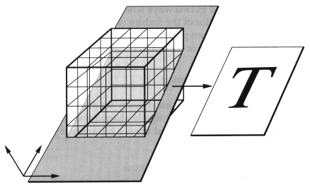
Thus, the displayable result from a 3D texture is not a volume of
pixels but a single 2D texture map, extracted from a slice through a
volume of texels and applied to a surface. However, it is possible to
build up a volume of data by repeatedly slicing through the 3D
texture and applying that to a series of "laminate" surfaces that
represent the volume. This could be used to simulate clouds or smoke,
for example.
Some examples of ways that 3D texture might be used are:
- Texture animations, such as moving people.
- Dynamically changing billboard textures, for instance, a tree
billboard could actually change appearance as its angle to the
eyepoint changes, even though it remains perpendicular to the
viewer.
- Smoke, cloud and dust cloud simulation.
- Multiple levels of detail for textured surfaces. This would
enable a large number of images to be blended sequentially under user
or simulation control.
Projected Texture
A new capability on RealityEngine enables non-orthographic texture
mapping. This means that a full RGBA texture map can now be obliquely
projected onto arbitrary surfaces in a 3D environment. When
projecting texture onto texture, this involves a straightforward
multipass technique. This is a powerful function enabling a whole
series of unique special effects:
- Multiple steerable lights, which are defined by a texture that
represents a cross section through the light cone. Radial and axial
attenuation are also supported.
- Aircraft shadow projection onto 3D objects such as terrain and
buildings.
- Wind effects, such as helicopter rotor wash and wind/wave surface
effects for maritime simulations.
- Support of true 3D shadows.
- Dynamic ship's wake projected onto moving waves.
- Projected reflections such as sun glint effects in space
applications.
Modulation and Decals
Each texture can be treated in two ways when being applied to a
polygon. When operating as a decal, the color of the texture replaces
whatever color is already inherant to the polygon. When performing
modulation, the texture color is blended with the color and properties
of the surface.
Texture Transparency and Contouring
Textures may have full or partial transparency set at any texel
location. This means that if the entire outer edge of a uniquely
shaped texture (such as a tree) is set transparent, the texture may
be placed upon a rectangular polygon, yet appear to have the outline
of a tree.
Perspective Correction
Per pixel computations are performed in the Raster Subsystem to
correct textures and fog for perspective distortions to insure that
no artifacts are introduced into the rendering process. These
computations do not impact the system performance.
5.3.3 Texture Performance
-
The texture fill rates on RealityEngine have been tuned to provide
high levels of scene depth complexity at fast frame rates and high
image quality.
The texture fill rate for RealityEngine is from 80 to 320MPixels per
second for writing of Trilinear MIPmap textured, subsample,
anti-aliased, full-color (RGBA), Gouraud shaded, lit, Z-buffered
surfaces into the frame buffer.
5.4 Anti-aliasing
-
Anti-aliasing is a fundamental feature of any true image generation
system. Artifacts caused by aliasing cause distraction in a
simulation environment, minimizing the level of realism of the system
and, potentially, causing negative training.
RealityEngine was designed from the outset to provide high-quality,
high-performance subsample anti-aliasing that is easy to use and
tunable for different system configurations. Most importantly,
anti-aliasing is provided on RealityEngine at no performance penalty.
Moreover, anti-aliasing with RealityEngine requires no sorting of
data and operates in conjunction with the Z-buffer for hidden surface
removal. This is unique at this level of system.
Anti-aliasing is accomplished by retaining subpixel information for
all vertices as they are transformed and processed through the
pipeline. Each vertex is computed with a subpixel accuracy in an 8x8
subpixel grid. Thus, there are 64 subpixel locations for each pixel
rendered. When deciding on how to color a pixel, the system samples
the subpixel grid with a certain number of samples per pixel, then
determines the pixel coverage based on the number of samples hit.
FIGURE 8 Example Subsample and Subpixel Layout for a
Pixel
The following anti-aliasing functions are available on
RealityEngine:
- Point Sampled
When performing point sampling, the system determines for each sample
location within the pixel whether that sample is covered by the
rendered polygon, vector, or point.
- Area Sampled
In area sampling, however, the system measures the percentage of the
pixel covered by the primitive and translates that into the nearest
covered point samples. In both cases, the color and Z values are
maintained for each sample, and performance should be the same. Area
sampling is suitable for long, thin polygons avoiding breakup.
5.5 Hidden Surface Removal
-
Hidden surface removal is performed by a high resolution Z-buffer on
RealityEngine. The use of a Z-buffer obviates the need for database
sorting and the use of unwieldy binary separating planes. Both of
these alternative methods increase the modeling effort and time
required to generate a database; they also restrict the overall
flexibility of the resulting simulation. The Z-buffer is particularly
powerful when a large number of moving models with articulated parts
interact with each other, such as an armored vehicle training
scenario. A Z-buffer-based system allows free movement of models
without any need for concern about occultation. Another area where
the Z-buffer is unique is when complex moving geometries intersect
with each other, such as the hull of a ship and moving waves, for
example.
RealityEngine handles Z-buffering and anti-aliasing simultaneously by
storing Z-buffer values for each subsample. This ensures correctly
anti-aliased polygon intersections. Resolution of the Z-buffer is
configurable up to 32-bit, providing high Z-buffer accuracy for
distant objects. RealityEngine supports correct occulting when
combining translucency and Z-buffering through the use of alpha
coverage masks. RealityEngine also handles polygons and textures
through the IRIS Performer environment.
5.6 Polygon Capabilities
-
5.6.1 Color
-
Colors may be specified in several different ways. For compatibility,
a color index mode is supported where an integer index value points
into a fixed size table. More common is the use of fully specified
Red, Green, and Blue (RGB) values for each color as it is set. Each
component of the RGB color may be defined with 8-bits for 24-bit
"true color", or for low light intensity applications, 12-bits per
component for 36-bit color and a wider dynamic range.
5.6.2 Smooth Shading
-
There is no penalty for performing smooth shading on objects rendered
with RealityEngine. The Gouraud shading algorithm is utilized to
smoothly shade the surface of each polygon using the current lighting
model.
When performing Gouraud shading, the Image Engines interpolate
between full RGB color values for a given pixel within a polygon to
enable smooth pixel to pixel color transitions. Advanced lighting
models enable time-of-day or local light sources. This provides for
clean, non-faceted rendering of complex objects in real-time, and may
be combined with transparency and texture for even more advanced
rendering effects.
5.6.3 Color Blending
-
When multiple occulting surfaces have partial transparency, the Image
Engines also perform color blending between each set of surfaces,
depending upon the alpha values associated with each vertex, or even
pixel (when texture mapping with alpha). These alpha values represent
a degree of translucency from 0 to 1 and enable the simulation of
windows, cockpit canopies, smoke, clouds, and other effects.
5.6.4 Lighting
-
Light sources may be colored to allow for effects such as time-of-day
lighting, where the color of the light as well as the intensity
changes over time. Light sources can be programmed with the following
parameters:
- Specular, for highlights and directional effects
- Diffuse, for broader directional effects
- Ambient, for environmental, non-directional effects
- Emission, for self-luminous surfaces, vectors, or points
- Color
- Attenuation with distance
- Local or infinite lights
Surface Properties
In addition to the four components above, a shininess component may
be set for the current lighting model, to handle different surface
properties. This component may be changed from object to object to
allow for a variety of different surface types in the environment.
This property, in addition to the light characteristics and the
surface color, may be combined with texture mapping and transparency
to provide the highest level of realism.
5.6.5 Atmospheric Effects
A programmable fog/haze function in RealityEngine allows users to set
arbitrary fog color, which may then be blended in a depth-dependent
fashion with the color of each pixel to be affected by the fog. This
can be applied to the whole scene or controlled independently for
differeent objects in the scene; for instance, light points may be
less attenuated than surfaces in fog. This is sometimes known as per
pixel fog. On RealityEngine, it is fully corrcted for perspective
distortion.
The fog is computed by means of a programmable function that the user
can control by loading the requisite parameters into the system fog
table. Alternatively, there are a number of standard exponential
functions that can be used.
5.6.6 Polygon Performance
-
The main focus of RealityEngine for polygon performance is for
polygons that are of high image quality, that is, textured,
anti-aliased, lit, smooth, shaded, and so forth. This is important
for image generation applications, since the majority of the imagery
that is being processed by the graphics subsystem is generally of a
complex nature.
RealityEngine has been designed to address these requirements in two
respects. The first is that the system can transform in excess of
210K textured, anti-aliased, Gouraud shaded, lit, Z-buffered polygons
per second. This approaches an order of magnitude faster than
previous Silicon Graphics systems. The second is that the graphics
subsystem has been designed with considerable elasticity. Two
high-capacity FIFO buffers are provided, one between the CPU
subsystem and the Geometry Engine and one between the Geometry Engine
and the Raster Managers. These effectively allow the pipeline to
exhibit considerable parallelism, enabling balanced throughput in the
graphics pipeline.
5.7 Video and Display Output
-
-
RealityEngine has an innovative and flexible display subsystem
capable of scanning the digital frame buffer out to video at varying
resolutions and pixel timings. High-speed digital-to-analog
converters (DACs) combined with custom circuitry enable software
programmability of video output formats without requiring any
hardware or PROM changes.
5.7.1 Programmable Video Timing
-
RealityEngine incorporates advanced circuitry for generating a
programmable pixel clock. The pixel clock controls the rate at which
the frame buffer is scanned out to a video signal. The standard
system runs at a resolution of 1280x1024 pixels, which are output at
60Hz non-interlaced.
5.7.2 Standard Formats
-
To provide users with as much built-in flexibility as possible,
RealityEngine systems are delivered with a broad range of
software-selectable video formats, from NTSC to standard 1280x1024
high-resolution, to HDTV.
5.7.3 Composite Output
-
In addition to the programmable pixel clock, which provides for RGB
output at a wide variety of video timings, RealityEngine has standard
hardware for the generation of a composite video output from the
standard system, to enable users to connect video recorders directly
to the system.
5.7.4 Genlock
-
To assure that RealityEngine graphics subsystems may provide video
output that is synchronized with other video sources or pipelines, a
standard Genlock capability is provided. Genlock assures that
multiple video sources all start scanning out their frames at the
same time to get frame-synchronized multi-channel output.
5.7.5 Multichannel Video Output
-
The optional VideoSplitter/2 board may be utilized for each graphics
pipeline to provide for up to six independent channels from a single
graphics pipeline. The board takes the digital, ordered pixel output
coming off the pixel bus from the XMAP processors of a graphics
pipeline and allows the user to specify up to six separate
rectangular areas to be sent out of the frame buffer to independent
component outputs. The board supports two different, simultaneous
video timings, with one timing supporting two outputs and the other
supporting four.
Since the VideoSplitter/2 takes the output from the Display Subsystem,
it can handle up to 2.6 million pixels in total. This means that a
single pipeline can generate, using VideoSplitter/2, two 1280x1024
60Hz displays simultaneously.
Section 6: Host Subsystem
6.1 The HI-CIG Concept
-
The benefits of including host and image generation capabilities in a
single system include reduced integration, fast response, and
simplified support. RealityEngine provides extensive host capabilities
with an advanced, symmetric multiprocessing (SMP) computational
subsystem. This subsystem combines parallel CPUs, memory, secondary
storage, and I/O to provide the ability to calculate real-time vehicle
dynamics, communicate with external communications boards and devices,
and access databases in addition to being able to generate
visual imagery.
6.2 Computational Capabilities
-
Depending on chassis configuration, RealityEngine can support from one
to eight CPUs in a parallel processing environment. Three RISC
processor types are available: R3000 (33MHz), R4000 in single
processor configurations, and R3000 (40MHz) in multiprocessor
configurations. Table 5 summarizes the CPU configurations and
performance available.
TABLE 5 RealityEngine: CPU configurations and
Performance
Simulation applications often lend themselves naturally to
multiprocessing. Typically, multiple simulations operate concurrently
(as in flight dynamics, engine model, and landing model), and results
from these calculations are required simultaneously for determination
of the update of vehicle position. RealityEngine multiprocessing can
be implemented at many levels, including the job, process, and
procedure levels. Multiprocessing tools and parallel compilers assist
in the development of real-time multiprocessing applications.
6.3 Real-time Operating System
-
6.3.1 REACT
-
Silicon Graphics' IRIX operating system is based upon a
POSIX-compliant version of UNIX System V3. It has, however, required
special modifications to support multiple processors, a concept not
covered by standard UNIX. These special functions at the heart of IRIX
have been combined under the banner of REACT, the RealityEngine Time
Access Technology kernel.
REACT offers a set of system calls that enable real-time operation of
systems running IRIX. Because real-time functionality is key to the
operation of simulators, REACT acts as the core of the system's host
capability. REACT provides deterministic response to interrupts and
deterministic dispatch latency.
Some of the key features of REACT include:
- Standard UNIX with deterministic response
- Fast total interrupt response: < 200 microseconds
- Shared-memory symmetric multiprocessing with full user control
over system resources
- Highly productive software development environment
- High-performance networking
6.3.2 Deterministic Response
-
UNIX was originally designed to distribute CPU time and other system
resources equally among users of a time-sharing system. As a result,
predicting precisely when any event will occur in a generic UNIX
system is impossible. IRIX with REACT includes the following
extensions to generic UNIX which, together, result in a fully
deterministic system suitable for real-time applications:
- Interruptable Kernel
- Precise process Priority Control
- Non-degrading Priority
- Locking Memory Pages
- Processor Isolation
6.4 Development Environment
-
One of the benefits of a deterministic system that supports a full
UNIX-based operating system is a rich development environment that
enables rapid generation of tuned simulation applications on the
target system, not on a dissimilar, remote machine. This reduces the
cost of the installation and ensures that the application is
developed in the context of the final operating environment. Some of
the tools available in this environment are:
- Wide range of compilers
- Multiprocessing tools
- IRIS Graphics Library (GL), an extensive 3D graphics library
- Image Processing Library
- Graphically based profiling and debugging tools
- CASEVision WorkShop, a CASE development environment
- IRIS Performer, a simulation-specific development and run-time
environment
Section 7: IRIS Performer
Visual Simulation Development Environment
-
As low-cost simulation applications evolve, two key elements are
becoming increasingly apparent:
- There is a demand for deterministic, high image quality and
performance at low cost
- The image generation system should be flexible, evolvable, and
capable of handling special effects
The combination of RealityEngine and IRIS Performer presents a unique
opportunity to provide both of these elements for the first time in
the low-cost visuals market. The goal is to provide developers with
software tools that enable them to create high-performance simulation
applications quickly and easily on Silicon Graphics systems. IRIS
Performer reduces the time required by developers to create a new
generation of innovative, low-cost, real-time, deterministic
simulation systems.
7.1 Advantages
-
IRIS Performer offers functionality in a number of key areas:
- High Performance
IRIS Performer maximizes image generation throughput, using multiple
processor task partitioning, efficient database traversal, and highly
optimized polygon rendering.
- Rapid Development
IRIS Performer provides an easy-to-use interface that reduces user
application development time and reduces the need to possess intimate
knowledge of the hardware platform. This permits developers to focus
attention on the specific issues that make their simulations
unique.
- Rich Functionality
IRIS Performer implements advanced image generation features required
in sophisticated out-the-window simulation applications. These
features include frame synchronization, system load management,
atmospheric effects, raster light points, and spatial inquiries.
- Enhanced Portability
Using IRIS Performer, applications are developed around a fully
supported, simulation-specific user interface that will evolve over
time and enable simple upgrades of simulation systems to future
hardware architectures.
- The Open Architecture Image Generator
IRIS Performer is not a closed book. It is fully extensible and
provides an environment that makes the addition of new functions and
effects a simple exercise. This enables the image generator system to
be adapted readily to a variety of applications as well as being
capable of being evolved to meet future requirements.
7.2 The Main Elements
-
-
IRIS Performer is a toolkit that provides libraries for obtaining
optimal graphics performance and for creating visual simulation
applications. It consists of two libraries: the Rapid Rendering
Library and the Image Generation Library.
7.2.1 The Rapid Rendering Library
-
This is a low level library that provides high speed rendering
functions, state control, and other machine oriented functions.
The Rapid Rendering Library consists of a number of facilities
required in most simulation and real-time graphics applications:
- High-speed rendering functions (GeoData)
- State managed rendering (GeoState)
- State management and mode control
- Display list rendering
- Extensive set of math routines
- Intersections
- Color tables
- Asynchronous file I/O
- Memory allocation
- High speed clock
7.2.2 The Image Generation Library
-
This higher-level library, built on top of the Rapid Rendering
Library, provides an environment for creating, updating, and rendering
a scene database at fixed frame rates. It is a rapid prototyping
environment that utilizes the Rapid Rendering Library functions to
create a multiprocessing, automated database rendering system. The
primary functions are:
- Hierarchical scene graph
- Multiprocessing (parallel simulation, cull and draw processes)
- Overload and frame management
- Level-of-detail model management
- Rapid culling to the viewing frustrum
- Intersection testing
- Dynamic coordinate systems
7.3 Key Functions
-
-
The following subsections describe the most important IRIS Performer
functions.
7.3.1 Database Structure and
Traversal
-
Traversal processing for complex hierarchical databases is the major
function of the Image Generation Library. It is the series of steps
required to transform a database and viewpoint definition into a
Rapid Rendering Library display list suitable for rendering.
The traversal processor constructs a special display list in the form
supported by the Rapid Rendering Library. Once the display list is
created, it is made available to the drawing functions of the Rapid
Rendering Library for processing through the IRIS Geometry
Pipeline.
7.3.2 Scene Culling
-
Many Simulated environments define a database that is much larger
than the maximum possible visual extent. Scenes are culled to
eliminate geometry not included in the observer's field of
view.
7.3.3 Level-of-Detail Management
-
Part of the real-time database traversal processing is the selection
of proper level-of-detail for multiple-representation models. Such
models exist as a series of progressively more elaborate models
representing increasingly finer model details. The traversal task
selects the appropriate model or model pair for rendering based on a
number of factors, which include:
- object range
- simulation field-of-view
- display surface size and resolution
- design eye-point to display surface range
7.3.4 System Load Management
-
Typically, simulation databases have uneven polygon density, which
requires control functions that maintain a steady frame rate. The
Image Generation library is designed to use a series of methods to
anticipate and smooth the effects of the dynamic nature of system
load in order to maintain a constant image update rate. The image
generation library uses the concept of stress as a measure of
system load. Stress measures the portion of simulation frame time
required to process a scene, through both the traversal and rendering
stages. This is then used to determine the levels of detail required
to maintain the desired frame rate in the scene.
7.3.5 Database Query
-
The Image Generation Library supports host inquiries regarding the
active database during real-time simulation activities. These
inquiries are spatial searches that:
- detect collisions
- determine height above terrain
- calculate ranges to nearest obstruction
- verify object intervisibility
7.3.6 Environmental Control
-
The earth/sky model provides the backdrop upon which the application
may draw a visual scene. It may be used in place of a "clear screen"
function and has several user selectable features:
- earth/sky color, texture, and selection
- horizon model
- fog and haze depth
7.3.7 Visual Effects
-
Weather effects provide effective visual simulation of a number of
natural phenomena that have been tuned for both performance and image
quality. The weather effects provided by the image generation library
consist of fog, haze, cloud layers, and atmospheric layer
transitions.
The Image Generation Library treats light points, which represent
point light sources, with special attention to visual simulation
needs. Color, intensity, shape, directionality, and pattern can be
defined to control their appearance. Lights can be steady, flashing,
rotating, and strobing.
7.4 The Sample Application
-
The sample simulation application provides a flexible, out-the-window
simulation application that demonstrates IRIS Performer's power and
flexibility. This sample application is layered above the Image
Generation Library and serves as an example of its programming model
and interfaces. It consists of source code implementing IRIS Performer
and a generic database.
Section 8: Reality Engine and Visual
Simulation
8.1 The Silicon Graphics Product Range
-
RealityEngine is a series of products that represent the high end of
a very broad product range of computer systems from Silicon Graphics.
With systems that range from desktop personal computers to
high-performance 3D workstations to supercomputer computational
servers. The Silicon Graphics product line offers solutions to the
whole range of simulation applications in addition to image
generation capabilities. A key advantage is that all Silicon Graphics
systems are binary compatible, which means that applications can be
developed on one platform and easily moved to another. This increases
overall flexibility and reduces development time.
8.2 Database Modeling
-
One of the areas that is key to the entire image generation process
is database modeling. It became apparent to visual systems suppliers
some time ago that an interactive 3D capability for database modeling
vastly improved the quality of the database, reduced database
construction time and provided the end customer with the ability to
maintain and evolve the databases on the simulator.
Silicon Graphics systems provide not only the interactive 3D
capability at low cost, but also the ability to edit complex textured
scenes in real time. As database requirements escalate and low-cost
visual systems capable of handling large quantities of texture
information become available, the emphasis of much of the database
modeling will be in the modeling of texture. It is important not only
to be able to view textures themselves but to view the whole scene in
real time. RealityEngine provides this capability by combining image
generation and database modeling capability in one system.
8.3 Other Application Areas
-
Other applications that the Silicon Graphics product range is
frequently used for are:
- Instrument prototyping and simulation
- Mission planning, rehearsal and simulation
- Host computational systems
- Instructor Operating Stations
- Air Traffic Control
- C3I applications
- Computer Based Training (CBT)
There is a wealth of third party software applications for Silicon
Graphics systems available in these areas, enabling rapid and cost
effective turnkey solutions to simulation problems.
Section 9: Reality Engine
Specifications
Product Scope
- A flexible image generation system for low-cost flight, ground,
space, maritime, and virtual reality applications
Visual Output
- 1 to 4 high-resolution (1280x1024) channels per system
- Up to 12 independent channels per system with individual
eyepoints
- Up to 5.2 million, textured, displayable pixels output from a
system
- Up to 320 million anti-aliased, trilinear, MIPmap textured
Z-buffered pixels per second fill rate per graphics pipeline
- User-definable display line rates
- Separate composite video output standard
Visual Priority
- Up to 32 bit Z-buffer fully integrated with anti-aliasing
- Coplanar surfaces
- Texture decal support
Surface Capacity
- Over 7000 polygons per pipeline at 30Hz [ie. in excess of
210K/sec]
- Polygons textured, anti-aliased, and Z-buffered
Texture Capability
- Photomap texture
- 4MBytes texture capacity standard
- Programmable texture map sizes from 2x2 to 1024x1024 texels
- Trilinear MIPmap texture capability
- 3D texture
- DetailTexture
- SharpTexture
- Up to 380 high-resolution (128x128) MIPmapped textures
- 4 to 48 bits per texel
- Lighting and smooth shading blended with texture
- Dynamic texture projection
- Environment mapped texture
Image Quality
- Up to 16 subsample anti-aliasing
- 8 or 12 bits per color component
- Lighting, shading, reflection, Z-buffering, anti-aliasing, and
translucency all combinable on same surface
Scene Management
- Database traversal, culling, and rendering
- Fade level-of-detail
- Overload management
- Frame rate control
Mission Functions
- Height above terrain
- Collision detection
- Range finding
- Line of sight
Special Effects
- Environment mapping
- Steerable landing lights
- Shadow casting
- Texture animation
- Articulation and geometry animation
- Horizon glow
- Support for extended special effects
- Directional shading and lighting
- 8 Configurable light sources, material properties control
- Full color interpolation on surfaces
- Lighting functions definable: ambience, diffusion, specularity,
shininess, emissivity, position, and color
Moving Models
- Over 100 simultaneous moving models (6 DOF)
- All models Z-buffered and anti-aliased at subpixel level
Weather/Environmental Effects
- Fog, haze, clouds
- Tunable fog functions
- Time of day
Transport Delay
- 83ms at 30Hz update and 60Hz refresh
Video Capabilities
- Standard 21 inch multisync monitor
- Digital video capability
- Selectable display from VGA to HDTV
- Genlock
- Independent NTSC or PAL video output standard
- Custom line rates
Translucency
- Up to 4096 levels of translucency
- Alpha to coverage function allows translucency, Z-buffering, and
anti-aliasing simultaneously
Software Tools
- IRIS Performer simulation development library enables flexible and
rapid application development
- Image Processing library
- Debug and performance tuning tools
- Multiprocessing tools
Light Points
- Raster based light point support
- Brightness and size vary with distance
- Independent light point fogging
- 3:1 trade off with polygons
- Directional lights
- Strobes, beacons, flashing, and rotating lights
Host Functionality
- Up to 8 multiprocessing RISC CPUs
- 30 to 286 MIPS and 5 to 70 MFLOPS
- REACT real-time system kernel
- Interrupt latency of <200 microseconds
- 4 to 6 VME slots
- High-speed disk and peripheral I/O support
- Up to 256MBytes of system memory
- ADA language
- Secure O/S. Trusted IRIX (Security level B1) available
Sensor Simulation
- Multiple color maps enable support for different sensor types
- Custom outputs configurable to suit display
Sound
- Optional digital audio board
- Programmable audio library
For more information please call
US: 1 800 800 SGI 1 (7441)
UK: 0 800 440 440
Australia: 008 802 677
Corporate Office
2011 N. Shoreline Boulevard
Mountain View, CA 94043
Copyright 1992, Silicon Graphics, Inc. All rights reserved.
Silicon Graphics, the Silicon Graphics logo, and IRIS are registered
trademarks, and RealityEngine, IRIS Performer, Geometry Engine,
VideoSplitter/2, SkyWriter, POWER Series, REACT, IRIS Graphics
Library, Crimson, IRIX, GL, CaseVision, Rapid Rendering Library,
Image Generation Library and Geometry Pipeline are trademarks of
Silicon Graphics, Inc.
MIPS is a registered trademark, and MIPS R3000 and R4000 are
trademarks of MIPS Computer Systems. UNIX is a registered trademark
of AT&T Bell Laboratories. All other registered and unregistered
trademarks are the properties of their respective holders.
Specifications are subject to change without notice.
RE-VisSim-TR(8/92)
[typed up by hand from the original 31 page document, from
8th to 13th of May 1998, by Ian Mapleson]
(check my current auctions!)
[WhatsNew]
[P.I.]
[Indigo]
[Indy]
[O2]
[Indigo2]
[Crimson]
[Challenge]
[Onyx]
[Octane]
[Origin]
[Onyx2]
[Future Technology Research Index]
[SGI Tech/Advice Index]
[Nintendo64 Tech Info Index]